Rotary engineering Frequently asked questions
If you can’t find the answer here, test our know how by sending us your question.
1. What rotary kiln or drum inspection checks are recommended?
The key to effective maintenance is the ongoing identification and monitoring of potential mechanical problems, along with the formulation and implementation of action plans to resolve issues before they affect your machinery and processes adversely.
British Rema recommends that rotary kiln or drum inspections are carried out on a frequent and regular basis during normal operations and during planned and unplanned shutdowns. Every inspection should be carried out in compliance with health and safety procedures at your plant.
We recommend that daily ‘walk-by’ inspections, weekly, monthly and annual inspections are carried out. We can assist you in identifying the individual elements of each of these different types of inspection. We also offer support in making sure this process is optimised for the specific type, age, and condition of the rotary equipment you use.
Inspections should be scheduled and carried out by an employee with responsibility for the specific rotary equipment. Detailed records of inspections should be kept, including details of any defects which are found, and any further developments and actions taken.
2. Why does my rotary vessel equipment require daily inspections and why are frequent adjustments required?
A rotary vessel (kiln or drum) is a shell with two or more rings. Each ring is supported on two rollers and the vessel shell is in constant rotation.
Roller supported rotary process equipment differs from ‘fixed’ equipment in many important ways. We can think of rotary equipment as being ‘dynamic; and fixed equipment as being ‘static’.
Static can be defined as ‘lacking in movement, action or change’. In this group, we would include equipment which is slow moving, sliding or not in continuous operation.
A dictionary definition of dynamic is ‘a process characterised by constant change’. Most dynamic machinery has enclosed parts and is rotating or reciprocating at high speed; the constant changes are usually consistent with each movement and can easily be accommodated in the design stage. The dynamic process of drums and kilns is of constantly changing magnitude due to many influences.
Dynamic
These constant changes are taking place continuously over time as this equipment normally operates 24 hours a day, seven days a week, which exaggerates the effects of the changes.
The changes originate from three sources:
1. Process: which may include, changes in product throughput; rotational speed; temperature of the product; feed size; and internal build-up or partial blockages inside the rotary kiln or drum.
2. External: for example, the impact of weather on equipment which is outside; the atmosphere and operating environment of the equipment; misalignment of support rollers; feed and discharge seals; extreme temperatures of equipment; vibration from equipment installed close-by; failures of the foundations, frames and piers; the design and location of the drum or kiln can also be a source of potential problems.
3. Material of construction of the drum: due to its own weight, the shape of the tyre and the shell not being round, the diameter measured on the horizontal plane will be larger than the diameter measured on the vertical plane. This is referred to as ‘Ovality’. This shape is constantly changing with the rotation of the drum, which will cause problems relating to fatigue on the material of the shell. This is considered during the equipment design process as it has a major influence on the life expectancy and reliability of the drum.
All these changes increase the loads and stresses which always exist on rotary equipment.
In contrast Static
Static process equipment, by definition, has little or no movement of parts and there is no significant change in shape or molecular structure of the metals. Static equipment is, therefore, is much easier to control by design.
All these important issues relating to dynamic rotary equipment are discussed in depth during our training seminar programmes, along with exploration of the causes, effects, inspection procedures, symptoms, measurement and adjustment techniques, allowable failure limits and solutions for successful operation and maintenance.
3a. What are the normally allowed hot rotary kiln or drum shell maximum temperatures?
British Rema recommends checking the specific construction material of your rotary vessel and the manufacturer’s instructions. In general, we recommend that 400oC is used as the maximum temperature.
3b. Why is a controlled warm-up important?
Mechanically, there is a need to control the warm-up temperature, primarily, because all the heat being generated does not pass from the shell to the tyre. This is the reason the tyre is not directly connected to the shell on heated rotary vessels. If the shell heats too quickly the expansion will not pass to the tyre fast enough and this can remove any allowed clearance and potentially crack the tyre or restrict the diameter of the shell in the area of the tyre. (The tyre is designed to allow an amount of diametrical clearance to allow the shell to expand. This amount of clearance can also be calculated to allow a site-specific expected amount of error.)
The expansion rate of the shell must be controlled to allow the correct operating temperature to be reached and operated without incurring damage. Uneven thermal expansion will cause distortion and bending of the shell which will damage the drive system, rollers, tyres and the mounting system and foundations.
The warm-up time can be checked easily by monitoring the amount of slippage between the tyre and shell during rotation at each tyre station. Our services include assisting in the process of establishing an appropriate warm-up period for your specific equipment.
4a. What is skewing?
Skew is the position of the roller axis with respect to turning axis of the shell. If the rollers are parallel, they have zero skew or are neutral. Zero skew means no axial thrust is created. If the rollers are not parallel, they are said to be skewed or ‘cut’. This creates an axial thrust that pushes the kiln either uphill or downhill.
As kiln shells are not truly straight the rotating axis at the rollers is not constant. Zero skew cannot be set with rollers that have a fixed base. This is only possible if the roller support base is allowed to articulate to follow the shell/tyre wobble.
Skew is created with a very small (0.004 to 0.040 inches, 0.1 to 1.0 mm) pivoting adjustment which changes the parallel relationship of the roller to the longitudinal axis of the rotating shell. It does not affect (to any significant degree) the position of the shell either in plan or elevation views. In other words, the roller is pivoted but the shell is not significantly raised or moved laterally.
This important concept must be understood completely before correct roller adjustments can be made. Thrust control by skewing may be the single most important adjustment which influences the optimum mechanical operation of the unit.
4b. Why do we need support roller skewing?
It is a requirement of most rotary kilns and drums to have the downwards force reduced by support roller skewing. Rotary kilns and drums which have a horizontal axis should not, in theory, require skewing if the all support rollers are parallel and are also on the horizontal axis. However, in practice, a small amount of skewing is often required to allow the thrust rollers to be in partial contact with the tyres during rotation. Only partial contact is desirable due to the small amount of misalignment which always exists on the tyres.
The optimum result is to achieve partial contact with the downhill thrust roller, however, it must be remembered that increases in rotational speed and load will increase the residual axial thrust.
British Rema offers roller skewing services. Skewing can also be included in the grinding of rolling surfaces. All of our grinding, alignment and repair technicians are trained in skewing procedures.
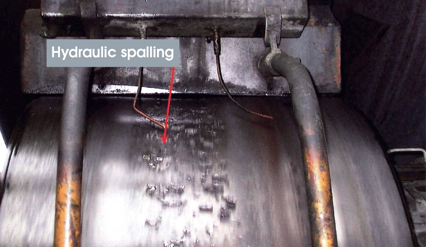
5. What is the most common cause of support roller spalling?
Spalling is the damage caused to the surface of rollers under the weight of the rotary vessel. It starts when small surface cracks start to develop and grow together over time, eventually causing pieces of metal to fall from the surface of the rollers.
The most common cause of support roller spalling is hydraulic compression. This is caused by the liquid used to lubricate the surfaces between the rolling surface of the tyres and rollers at the point of contact. Liquids can also be introduced to the rolling surfaces by leakage of cooling water, or spillage or excess from the lubrication applied to the bearings or associated equipment.
Liquids are non-compressible. When forced through the rolling contact surface pinch point the liquid pushes against the steel. This pressure can cause micro-fissures in the steel where droplets of liquid can become trapped and forced between the molecules of the rolling surface material. This fractures the steel on a microscopic level with every turn of the rotary vessel. Eventually, the cracks worsen and pieces of the roller surface fracture loose.
As spalling can also be caused by various mechanical issues, it is important to identify the root cause of the spalling. This is best done by one of our engineers who can carry out a detailed inspection of the equipment.
If the spalling and its causes are not addressed the consequences can be serious. Spalling can lead to extensive damage to the equipment, including failure of the tyre, rollers and bearings.
British Rema recommends the use of a dry lubricant, such as graphite blocks, to avoid the problems associated with spalling. Graphite blocks operating in contact with the rollers provide superior, compressible lubrication and allow for inspection during plant operation.
The range of services we offer includes resurfacing of the tyre and rollers to remove the damage caused by spalling using our patented grinding system. Often, resurfacing can take place whilst the plant is in normal operation. In addition, we can design, supply and install graphite block lubrication systems.
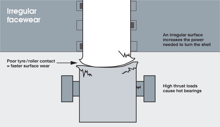
6. What causes ‘mushrooming’ at the sides of the tyres and support rollers?
‘Mushrooming’ is a deformation due to high loading at the edges of the rollers or tyres. This can be caused by over skewing; rolling surfaces that are not flat; or, problems relating to roller alignment.
When the edges start to “mushroom” the probability of cracks forming at the edges increases. Unless the mushroom shape is removed, cracking of the support roller or tyre will occur.
The causes of the ‘mushroom’ wear pattern will need to be addressed to prevent the problem recurring. We can resurface the tyre and/or roller by grinding or, if the damage is extreme, by cutting away most of the ‘mushroom’ and then grinding.
Our experienced technicians can perform this procedure to achieve the optimum operating condition which reduces thrust loads and the associated surface wear and equipment damage. Usually a reduction in the power consumption is also seen following these procedures.
7. Which is the best auxiliary drive system?
The purpose of the auxiliary drive system is to prevent damage to your rotary equipment in situations where the machinery stops. It is an emergency back-up system and is not designed to keep production going.
There are two main root causes of failure to consider:
1. Power supply
2. Mechanical
In the case of power supply loss, the solution is relatively simple and probably involves an auxiliary power supply such as an electrical generator or diesel engine.
If the failure is due to the mechanical drive this indicates equipment failure and the resolution is more complex.
Our engineering design team are experienced in resolving these challenges and can assist in the design, manufacture and installation of site-specific auxiliary drive systems.
8. What is causing the thrust roller to lift out of its bearing?
The position of the thrust roller in relation to the centre point of the rotary kiln or drum is critical to prevent lifting. The thrust roller must always be positioned slightly biased to the down-turning side of the kiln or drum. In this position the rotation forces the thrust roller downwards. If the thrust roller position is slightly on the upturning side of the rotary vessel the rotation will tend to lift the roller.
British Rema recommends the roller is positioned 1–2 mm on the down-turning side. We can determine the correct position required during our alignment measurements.
It is not safe to move a thrust roller when the machine is in operation. Care should be taken when removing or replacing a roller as the roller may lift out of the bearing causing the parts to fall.
9. Which is the best girth gear lubrication system to use?
British Rema recommends the use of constant loss spray lubrication systems operating with ‘dry’ lubricants such as suspended graphite or molybdenum.
Although named ‘dry lubricants’, these products contain liquid elements which act as carriers. As the spray is compressed in the mesh, the lubrication element builds a barrier between the gear and pinion.
The lubricant is applied in the correct quantity giving optimum life of the gear and pinion with minimum cost of lubricant and it allows visual inspection of the driving flank of the teeth.
We can design, supply, install, and commission spray lubrication systems appropriate for your application.
10. What is the maximum allowable wear on my support rollers?
As a guide, British Rema recommends that the rollers should be replaced at approximately 50% of their original thickness. It is at this point that the structural integrity of the roller is at risk of failure.
However, this is dependent on the design of rollers installed. In general, we recommend solid forged rollers. This type gives a longer service life and removes the risk of casting faults.
11. What is the cause of the horizontal lines appearing on the faces of the tyres, support rollers and thrust roller(s)?
These horizontal lines are usually caused by vibration coming from the drive gear and pinion mesh area. The vibration caused can usually be felt on the pinion bearings. The lines may be in sync with the tooth contact or multiples of the tooth frequency.
The causes can be;
- reduced root clearance of the teeth which will cause bottoming of the gears
- loss of teeth profile
- incorrect set up of the pinion and gear
- incorrect design
The solution will be dependent on the root cause. Once corrected, grinding of the rolling surfaces is recommended. British Rema supplies gears and pinions, supervision of installation, or total installation services, and grinding of the rolling surfaces.